![]() Email:sales04@bdhuazheng.com
Email:sales04@bdhuazheng.com
![]() Cellphone/ wechat/Whatsapp /Skype: +86 18330222302
Cellphone/ wechat/Whatsapp /Skype: +86 18330222302
I. Causes of multi-point grounding faults in transformer iron cores
1) The iron core is connected to the outer shell. Loose displacement of the iron core and metal components left at the lower part of the iron core (such as screw caps, metal powder and wires from the grinding of submersible pump bearings) can all cause the iron core to be connected to the shell, resulting in multi-point grounding faults of the iron core and abnormal grounding current of the iron core.
2) The iron core is connected to the clamp. The warping of the iron core, metal foreign objects, impurities, and other reasons can all cause direct or indirect short circuits between the iron core and the clamp, resulting in multi-point grounding faults of the iron core and abnormal grounding current of the iron core.
II. Identification method for abnormal grounding current of iron core
1) Grounding current testing method
The transformer iron core is grounded at a single point through a grounding lead, with a grounding current of milliampere level. When the iron core is grounded at multiple points, the current flowing through the grounding lead wire increases sharply. The magnitude of this current depends on the relative position between the fault point and the normal grounding point, that is, the amount of magnetic flux contained in the short-circuit turn. The maximum current can reach several hundred amperes. The common method is to use a specialized clamp ammeter to measure the current value on the grounding lead of the transformer iron core, and determine whether there is a multi-point grounding problem in the transformer.
2) Chromatographic analysis method
When the iron core of a transformer has multiple grounding points, the transformer will exhibit high or medium temperature overheating phenomena. Gas chromatography analysis of characteristic gas content in transformer oil shows that the total hydrocarbon content exceeds the attention value (150 µ L/L), with ethylene (C2H4) and methane (CH4) accounting for a large proportion, and acetylene content being low or unchanged. The chromatographic three ratio is usually "022" or "021".
3) Insulation resistance testing method
Measuring insulation resistance is a simple and feasible method for detecting whether there are multiple grounding points in the iron core. During the detection, the grounding lead wire needs to be disconnected first, and the insulation resistance of the iron core and clamp to ground should be measured separately to determine whether there are multiple grounding faults in the iron core and clamp. Measure the insulation resistance of the iron core to the clamp to determine if there is overlap between the two. This method cannot detect short circuits between transformer core pieces.
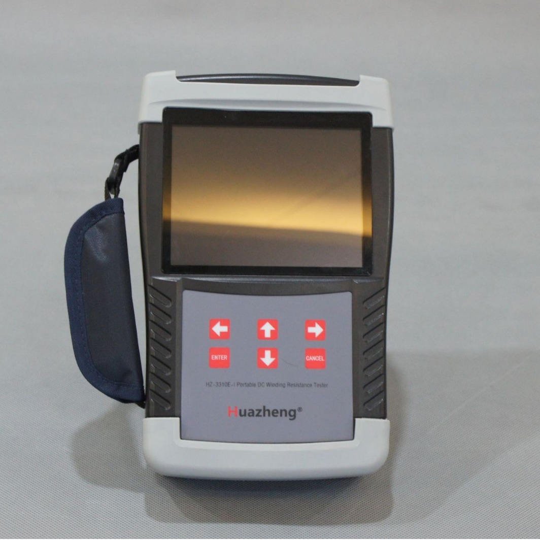
HZ-3110E-I Handheld 10A Transformer Winding Resistance Tester
