![]() Email:sales04@bdhuazheng.com
Email:sales04@bdhuazheng.com
![]() Cellphone/ wechat/Whatsapp /Skype: +86 18330222302
Cellphone/ wechat/Whatsapp /Skype: +86 18330222302
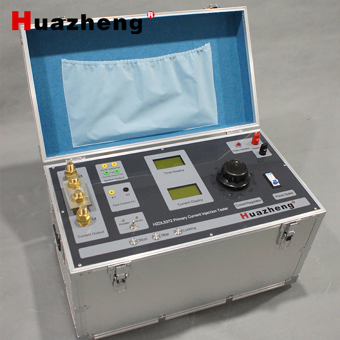
1. Connect the power supply, connect the current output terminal to the primary side of the tested current transformer, and connect K1 and K2 to the secondary side of the current transformer. Short circuit the normally closed switch, otherwise the test cannot be carried out
PS: In practical application testing, normally open and normally closed should be connected to the normally open and normally closed points of the relay protection device in the switchgear. If only testing the transformer, short circuiting the normally closed point is sufficient
2. Close the switch, use the toggle switch to select the wiring method for the current output terminal, series or parallel, press the start button to start the test, turn the handle to increase the current, and raise it to the required current
3. After reaching the required current, there will be some fluctuations in the current and the value will not be very stable. At this time, pressing the lock button can prevent the panel value from changing, making it easier to view the current transformer ratio data
PS: The lock button only serves to facilitate the observation of panel data and does not affect the actual current output. The panel value remains unchanged, which does not mean that the actual output current is stable and does not fluctuate.
4. After the experiment is completed, turn the handle to zero, press the stop button, turn the toggle switch, turn off the switch to cut off the power, and the experiment is over
HZ5372 1000APrimary Current Injection Tester
