 Email:sales04@bdhuazheng.com
 Cellphone/ wechat/Whatsapp /Skype: +86 18330222302


Email:sales04@bdhuazheng.com
Cellphone/ wechat/Whatsapp /Skype: +86 18330222302

Its main business is the production, manufacture and sales of electrical equipment and testing instruments.
The wiring for the variable ratio test looks simple, with only a few test clips, but it wasn't until we arrived on site that we discovered many details about which one to connect, whether to connect the neutral point, and the difference between single-phase and three-phase. Clarifying these questions can avoid most of the wiring reasons for 'test failures'.
General wiring sequence: Ground wire → Test wire → Power wire
No matter what type of transformer is being tested, the wiring sequence is always: first connect the instrument grounding pole to the ground (while confirming that the transformer chassis is also effectively grounded), then connect the high and low voltage test lines, and finally connect the power line. The dismantling sequence is completely opposite: first disconnect the power supply, then dismantle the test wire, and finally dismantle the ground wire. This sequence is an iron rule in any high-voltage electrical test, and the HZTTR80A manual specifically emphasizes it with a horizontal box, not an optional one.
Three phase transformer wiring
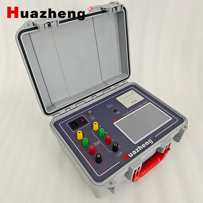
Four terminals on the high voltage side: yellow (A), green (B), red (C), and black (N), corresponding to the A, B, C, and N terminals on the high voltage side of the tested transformer. The low voltage side is also yellow (a), green (b), red (c), and black (n).
Whether to connect the neutral point depends on the connection method
This is the easiest place to confuse. The following connection methods do not require a neutral point N to be connected:
Y/yn
YN/d
D/yn
D/zn
Y/zn
autotransformer
Only when the neutral point on the high or low voltage side needs to be led out for measurement (such as some YN/yn transformers), is it necessary to connect the N line. If you are unsure, you can first use blind testing mode to test again, and the instrument will tell you the actual connection method before deciding whether to connect the N line.
Wiring of single-phase transformer and PT
Single phase transformer and PT testing are simpler: only use the yellow and black test clips on the high voltage side, and the yellow and black test clips on the low voltage side. The remaining green and red test wires can be left unconnected in the air.
How to dispose of unused test clips
The instruction manual specifically reminds that all unused test clips must be isolated from each other, from the ground and operators, and cannot be casually placed on transformers or together. During the testing process, the instrument has an output voltage. If the suspended clamp comes into contact with other conductors, it may interfere with the measurement results or cause electric shock.
According to this rule, the probability of problems occurring during the wiring phase will be much lower. What are the wiring rules for the ratio tester?
HZTTR80A Transformer Turns Ratio Tester


Contact : Summer Xu

Position: Sales Manager

Email: sales04@bdhuazheng.com

Cellphone/ wechat/Whatsapp /Skype : +86 18330222302

Address: Unit 3, Building 9, No. 3099 Xiangyang North Street, Gaokai District, Baoding,Hebei,China,Zip: 071000

 sales04@bdhuazheng.com
 +86 18330222302
 +86 18330222302
 +86 18330222302
 +86 18330222302
